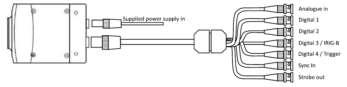
The 1/0 on a i-SPEED 211 and 221 camera is accessed via a all signal that plugs into the second connector below the 6 pin power connector.
Digital 4 / Trigger inRecording can be stopped either with a trigger switch or by a low or high external signal.
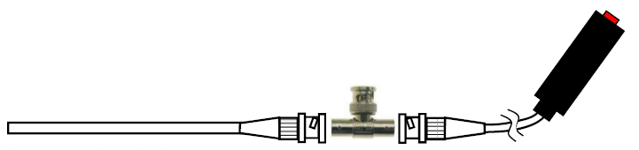
Using a trigger switchTo use a hand trigger cable then connect using BNC T connector with the Trigger In connector on the breakout cable.
 Using a external trigger input
Connect the Trigger In connector with an external trigger. Enable External Trigger in the Camera 10 menu of the Control 2 series software and decide whether a rising or falling edge of the signal will stop the recording.
Sync in The Sync In connector allows the user to synchronise one or more cameras with an external signal. Before using this feature, enable Sync In in the Camera 10 menu of the Control 2 Series software and decide whether a rising or falling edge will start synchronisation.
Note : Sync out activates a strobe that corresponds to the exposure time of the camera.
Analogue in
The analogue input is adjusted to deliver a value of 255 for 2.55V input voltage.
Digital 1,2,3
These signals are TTL input signals and are used as process signals, which are superimposed to the image.
Digital 3 / IRIG-8
If the camera is equipped with the IRIG-B option then several cameras can be synchronized wirelessly. The feature must be enabled in the software.
Strobe Out
Strobe out supplies the synchronisation, trigger, or recording status of the camera.